The Summary page is the initial Design Parts Sync page that loads in a new or existing tab (CIP Design Parts Sync: <DESIGNNAME.DSN>), displaying the Summary Information, Part Status Report, Display Mode, Export, and User Settings, and Sync Actions. Data displayed on the summary page will be refreshed each time you open the Design Parts Sync tab, click the Refresh ![]() button, complete an Auto Sync, or return from Processing page after processing selected parts.
button, complete an Auto Sync, or return from Processing page after processing selected parts.
Click the ![]() link in the title bar to open the User Guide to this section.
link in the title bar to open the User Guide to this section.

Design Parts Sync - Summary View
2.Display Mode, Export, and User Settings
The Summary Information displays the following data:

Design Parts Sync - Summary Information
▪Refresh ![]() button - Click to refresh the Summary Information and Part Status Report for the current design.
button - Click to refresh the Summary Information and Part Status Report for the current design.
▪Design Path and File Name - Design Path and File Name of the current design (DSN) file in the form of <Design Path>\<Design File Name>.
▪RefDes - The total number of RefDes (Part References) used on the current design.
▪Parts – The total number of unique Parts (PART_NUMBERs) used on the current design.
▪Last Checked (Date/Time) – The last date and time the summary page was loaded (initially invoked, refreshed, and after processing).
The Display Mode and User Settings determine how the data is displayed in the Part Status Report. The current Display Mode is always shown above the Part Status Report, while the rest of the settings can be accessed by clicking the Settings ![]() button. The current report can be exported using the Export
button. The current report can be exported using the Export ![]() button.
button.
•Display Mode - This allows the Part References (RefDes) used on the design to be shown using one of three modes (Single, Delimited, Compact), similar to the options when viewing or exporting CIP BOMs. Each time the Summary page loads in a new tab, it uses the Default Display Mode from the User Settings below, which is initially set to Single.
(Current) Display Mode
oSingle - Each reference designator is shown on a single line. *This is the initial default for all users.
oDelimited - Each part number is shown on a single line where reference designators are shown as a comma separated list.
oCompact - Each part number is shown on a single line where reference designators are shown as ranges or a comma separated list.
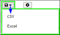
•Export - Use the Export ![]() button to save the Part Status Report in either CSV or Excel format.
button to save the Part Status Report in either CSV or Excel format.
•User Settings:

Settings
oDefault Display Mode - Configure the default Display Mode (Single, Delimited, Compact) for the Part Status Report, similar to the (on-the-fly) Display Mode setting. *Single is the initial default for all users.
oDefault Selection State - Configure the default selected check boxes (All, None) for the Part Status Report. *All is the initial default for all users.
oDefault Sort - Configure the default sort order (Part Reference, PART_NUMBER then Part Reference) for the Part Status Report. *Part Reference is the initial default for all users.
oSummary Displayed Fields - This shows the PART_NUMBER and a cumulative list of all CIP Fields configured to Transfer to Design for all component views. By default, all fields set to Transfer to Design in CIP will be shown on the right side, meaning they will be shown in the Part Status Report. Click and drag a field up or down the list on the right to reorder it. Click the![]() button to move a field back to the left side so it will not be shown in the Part Status Report, though it will still be used to determine the Part Sync Status.
button to move a field back to the left side so it will not be shown in the Part Status Report, though it will still be used to determine the Part Sync Status.
oClick ![]() to save your updates or
to save your updates or ![]() to discard them.
to discard them.
The Part Status Report is displayed in table form and includes the data columns below for all parts placed on the design, as of the date/time shown in the Summary Information at the top of the page. The Part Sync Status and Part Reference columns are always shown, while the rest of the columns can be shown/hidden and reordered using the Settings ![]() button. Data displayed in the report may be exported using the Export
button. Data displayed in the report may be exported using the Export ![]() button, with options for CSV and Excel output.
button, with options for CSV and Excel output.

Part Status Report - Example

Part Status Report - Part Sync Statuses
The Part Sync Status, Part Reference, PART_NUMBER, and other CIP Fields configured to Transfer to Design will be highlighted and labeled based on the Part Sync Status scenarios above.
▪Check Boxes - The left-most column consists of a Select All/None check box, followed by individual check boxes associated with each data row. e.g. Design Parts that are Found - Up to Date, Found - Up to Date (TMP), etc. will not be selectable because their CIP transferred fields are already up to date so there is no action to take.
▪Part Sync Status - This indicates the status of each part (Part Reference) placed on the design, relative to its PART_NUMBER in CIP. The Part Sync Status, Part Reference, and PART_NUMBER will be highlighted and labeled based on the Part Sync Status values shown above. In some cases, the same placed part may meet multiple criteria, in which case the Part Sync Status displayed will be prioritized as shown above. *This column is always shown, not able to be reordered.
oPart Reference and PART_NUMBER will also be highlighted under certain conditions as shown above in the Part Status Report - Part Sync Statuses.
oWhen any CIP Field transferred to Design Property is out of date with CIP, the value of the Design field in the Part Status Report will also be highlighted.
▪Part Reference - This column lists all of the Part Reference(s) for a given row. The number of Part References depends on the Display Mode and number of unique records based on the references and PART_NUMBER shown. The Part Reference value will be will be highlighted under certain conditions as shown. *This column is always shown, not able to be reordered. In Single and Delimited display mode, the Part References are clickable links that can take you to the associated part on the design. In Compact display mode, only rows with a single Part Reference are links.
▪PART_NUMBER - This column lists the associated PART_NUMBER for the Part Reference(s) on a given row. This can be grouped to one or more Part Reference(s) depending on the Display Mode and number of unique records for the RefDes and PART_NUMBER shown. *While this column can be hidden using the User Settings, it is not recommended. The PART_NUMBERs are clickable links that can take you to the associated part in a new CIP tab.
▪Source Library and Source Package - These are Capture properties that include the path/location of the schematic part along with the schematic part name itself. When a part is placed on the design using CIP, the Schematic Part field will be used, along with the path(s) from your Capture.INI file (unless the explicit path is specified in the Schematic Part field). There are various ways to specify the Schematic Part (e.g. CAP, CAPACITORS\CAP, \\CENTRALLIBRARY\CAPACITORS.OLB\CAP, etc.) so there is logic that tries to account for this when comparing the Source Library and Source Package to the Schematic Part value in CIP.
oIf an issue/mismatch is found, you must resolve it by (1) updating the Schematic Part value for the part in CIP, (2) updating the path(s) in your Capture.INI file, or (3) using the Replace Cache feature in Capture. This is because the Source Library and Source Package fields themselves are not editable properties in your Capture design. The appropriate solution will depend on each case found.
▪Other Design Fields/Properties that are configured to Transfer to Design in CIP - The rest of the fields shown are specific to your CIP database and consists of the fields that your CIP has set to Transfer to Design and that are configured to be shown in your Design Parts Sync's User Settings.
oWhile not required, these CIP fields are most often set to transfer to design from CIP: Value, Description, PCB Footprint, ALT_SYMBOLS, CLASS
oOther key parametric data fields that are commonly set to transfer to design from CIP: Package Size, Package Height, Tolerance, Rated Voltage, Schematic Part, etc.
▪Replace Part - This context menu can be invoked by right-clicking (RMB) on a row for a single RefDes (Single display mode) or group of RefDes (Delimited or Compact display mode) to be replaced. Follow the instructions to continue with Part Replacement from Design Parts Sync.
The Sync Actions are used to update the transferred design properties for the parts on your design with the associated field data from your CIP database. Select the check boxes for the desired parts (Part References aka RefDes) and then click one of the two sync options. Hover over either button to see a tooltip with a more detailed description.
![]()
1.![]() - This will open the Processing page and allow the user to review the selected parts (RefDes) to process, grouped by part number, and decide whether to
- This will open the Processing page and allow the user to review the selected parts (RefDes) to process, grouped by part number, and decide whether to ![]() ,
, ![]() , or
, or ![]() . All of the Part References associated with a single PART_NUMBER are grouped together and can be processed together as well, but individual items can be deselected if you do not wish to sync them at that time.
. All of the Part References associated with a single PART_NUMBER are grouped together and can be processed together as well, but individual items can be deselected if you do not wish to sync them at that time.
![]()
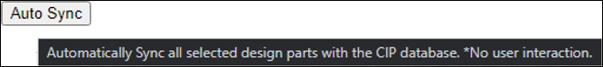
2.![]() - Automatically Sync all selected design parts with the CIP database, without user interaction. The Processing page will not be shown in this case.
- Automatically Sync all selected design parts with the CIP database, without user interaction. The Processing page will not be shown in this case.